Current events
A solidification of the plans
While I've been away, I've not quite completely left things alone.
For example, I had quite a bit of time in planes and stuck in airport terminals. My 12in. Apple PowerBook is not only small - fitting neatly into a pocket of my backpack (I've never seen the need for a laptop bag, they scream 'Steal Me!') - but also runs gschem just fine.
So I passed the time on the plane from Houston to Salt Lake City and back making symbols for the memory and the W5100, and also experimenting with transforming a schematic into a netlist and PCB layout with my own symbols. Then, I made the CPLD symbol, and on the plane from Houston to Gatwick, started on the schematic proper. I nearly missed the plane from Gatwick back to the Isle of Man, I got so engrossed.
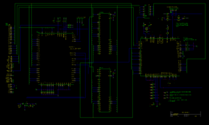
If you go to the image on the right, make sure you download it and zoom in fully, it's about 3000x2000 pixels or so - with so many pins on the chips the schematic gets a bit large. On this schematic, I'm explicitly showing power pins (often, people omit them from schematics). There are no less than 3 voltages used - 5v, 3.3v and 1.8v, as well as analogue 3.3v and analogue 1.8v - no less than 5 power nets. Also, there's a bit more than the usual decoupling used, so I want to show this explicitly. (I'll modify gschem's 74245 symbol to include power). It's a work in progress and not yet complete; in particular, I've not yet decided the pin assignments for the CPLD, nor the precise details of the reset circuit, and I need to finalise the ROMCS circuit (and have it compatible with the Spectrum +3). The through port is not shown on the schematic (and I don't intend to show it, except for indicating where A15OUT should connect).
Once the final prototyping is complete, and I've tested the basic socket library (to shake out any hardware problems I've not yet discovered), the next step will be the PCB. I intend to make 10 prototypes, using PCB Train as a board maker (the same board maker used for Papaya Labs DivIDE). My plan for the PCB is to make it pretty small - around 10cm by 5cm - if I can keep it short, then the through port can be just on the back of the PCB. This may require a 4 layer board.
While in Houston, I visited EPO - it's a handy component shop with all sorts of interesting stuff. I picked up a few 74HCT245 ICs while I was there - if you read down to some older entries here, you'll see the problems encountered with when 0xFF is read from the W5100 - which doesn't have the oompf to drive the Spectrum's long bus (with all the parasitic capacitance that implies). The '245 allows me to separate the Spectrum's bus from the W5100's data I/O pins, so the W5100 is only driving the lines to that one chip, with nice high impedance FET inputs. Putting the '245 on the breadboard completely solved the problem, even after removing all the 4.7k pull up resistors. I've decided I'll use the '245 rather than putting a bidirectional buffer into the CPLD, since the bidirectional buffer uses a heap of macrocells (about 25!) I could use for something that would take several chips to implement.
Winston 21:55, 19 February 2008 (UTC)
