Difference between revisions of "Current events"
| Line 20: | Line 20: | ||
I've also run out of jump wires for breadboarding (or at least, ones of a useful length). It seems a bit odd since I breadboarded an entire Z80 based computer using the wires I have now, but somehow I've managed to use nearly all of them. However, once I've done more complete testing on the memory and paging, it'll be time to plug in the W5100. | I've also run out of jump wires for breadboarding (or at least, ones of a useful length). It seems a bit odd since I breadboarded an entire Z80 based computer using the wires I have now, but somehow I've managed to use nearly all of them. However, once I've done more complete testing on the memory and paging, it'll be time to plug in the W5100. | ||
[[User:Winston|Winston]] 20:08, 13 January 2008 (UTC) | |||
== Major breadboarding session on the way... == | == Major breadboarding session on the way... == | ||
Revision as of 20:08, 13 January 2008
Testing the new CPLD
I had been planning to work on other projects this weekend, and not do anything at all with the Spectrum ethernet prototype... but I shot myself in the foot with the other project (due to sloppy thinking that 5 minutes careful thought would have prevented), so I worked on the ethernet project instead.
The goal: test the new CPLD works at all; it's a 3.3 volt chip with 5v tolerant I/O. Eveything in the Spectrum should be TTL compatible (so 3.3v is a perfectly valid logic 1), as should be typical 5 volt CMOS flash and static RAM. However, there's nothing worse than spending hours making a PCB then discovering it can't work (ever), so to the breadboard it was.
I had actually wired up half the circuit in the week, then finished it off today.
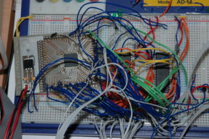
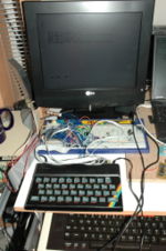
It didn't work. The usual random colour attribute vomit on the screen when I powered up, which is so familiar to anyone who has either a Spectrum with bad lower RAM, or has just plugged in a faulty peripheral. So I unplugged, and checked the Spectrum still worked (which it did). I then removed the memory and the connection to the ROMCS level shifter so only the CPLD was connected - with the same result. The CPLD was powered and apparently working, so I unwired everything - sure I had a short. I rewired, and tested the Spectrum at each major checkpoint (first the address bus; OK - then the data bus; OK - then the control lines - vomit). I started removing connections to the control lines (all of them CPLD inputs - nothing actually driving a signal into the Spectrum yet), and it started to work as soon as I removed the RESET connection.
It turns out that the RESET line gets stuck at about 0.2 volts when connected to the RESET input on the CPLD. If you momentarily touch RESET to +5v, it un-sticks and everything works just fine. Testing the voltage level when RESET is high shows that it's sitting at 3.3v, which suggests the 5v tolerant I/O on the CPLD is done by clamping the input with a zener diode - but there must be something more to it if it causes RESET to stick low (if the 5v tolerance is just an on-chip zener and resistor, it shouldn't affect stuff until the voltage exceeds 3.3v). Still, the input impedance must be pretty high since the other I/O lines don't bother the NMOS circuits in the Spectrum. I will have to examine the Issue 4 Spectrum schematic to find out why the CPLD causes it to stick low. The fix (for now) is to add a 4k7 pull-up resistor to the RESET line - it functions fine like that.
With that mystery solved, I added the flash ROM and 128k static RAM back to the circuit. I also modified the routine I've been testing the hardware with, so it resides entirely in page 0 of flash (which is permanently mapped to 0x0000-0x0FFF when our memory is paged in), and the workspace for the character printing routine into our RAM, instead of upper RAM on the Spectrum. More testing is needed (such as the paging mechanism for the memory map between 0x1000 and 0x2FFF) but that can wait until tomorrow. Test code can be viewed here ( [1] ) - I use sjasmplus, and 'testtraps.asm' assembles all.
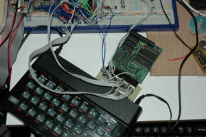
I also did some rudimentary compatibility testing. First, with my own diagnostics board since this is dirt simple and hopefully I can understand it if it goes wrong. Compatibility with downstream devices with their own shadow ROMs is peformed by nailing A15 high on the through port whenever we're paged in (which stops anything on the through port mapping its memory, since it will see an address >= 0x8000, rather than one in the lower 16k). This went fine - the RESET routine running from the flash on the breadboard, and then the diagnostics card getting paged in and running its tests (which all completed successfully). I tried the same thing with the DivIDE - again, it worked fine, the RESET routine running from my flash, and then the DivIDE getting initialized as normal.
I've also run out of jump wires for breadboarding (or at least, ones of a useful length). It seems a bit odd since I breadboarded an entire Z80 based computer using the wires I have now, but somehow I've managed to use nearly all of them. However, once I've done more complete testing on the memory and paging, it'll be time to plug in the W5100.
Winston 20:08, 13 January 2008 (UTC)
Major breadboarding session on the way...
I have the basic CPLD design now more or less done and simulated within Xilinx ISE, all it needs to do is actually work. So I have some pin-thru-hole flash (Am29F010) and static RAM (Mitsubishi M5M51008B), both 128kbyte, for testing the memory. The current CPLD design (which includes the pager and instruction trapper) fits easily into the XC9572 with many macrocells free. I still have a bit more to add (software enable/disable RST 8 trapping, NMI through, soft enable/disable W5100 interrupts) but there should be some macrocells left over for 'luxury items'.
More on the memory map and paging mechanism on the Memory page.
My plan is to test with just the flash and RAM at first, then add the W5100 breakout board, which should be a simple matter of connecting it to the data/address bus and writing a little bit of code to set it up. While theoretically the circuit is just a straightforward adding-memory-to-the-bus type of affair, I know from my testing of the W5100 with my ALIAC-2 Z80 based computer is that the W5100 seems to load the bus. The Spectrum's NMOS parts just aren't going to be as good at driving heavy loads as the ALIAC-2's CMOS parts, so it remains to be seen whether all the signal lines to the W5100 will need buffering.
Winston 22:41, 5 January 2008 (UTC)
Back to work for the new year
What with the usual holiday festivities, I've not really done much on the project since making the breakout board (except testing the board actually works), and doing a bit of diagnostic work on a new dead 48K Spectrum+ that someone sent me.
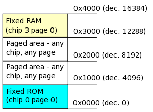
I'm getting close to the design being settled for the memory map. The current intention is to do the following: treat all memory (including the W5100) as 4K pages, with 2 pages fixed in the memory map (so when an event happens, we're guaranteed to have a certain page of flash ROM and a certain page of workspace mapped in), and 2 pages that can be mapped from any 4K page of RAM. The memory map will look like this, when mapped into the Spectrum's lower 16K:
- 0x0000 - 0x0FFF - page 0 of flash ROM. Contains initialization code, socket library, various low level function calls.
- 0x1000 - 0x1FFF - Any 4K page of any memory.
- 0x2000 - 0x2FFF - Any 4K page of any memory.
- 0x3000 - 0x3FFF - page 0 of the onboard static RAM. Workspace, system variables, jump table.
The only decision left is this: To allow room for future expansion, the registers for the pagable areas are all 8 bit (allowing for up to 8 megabit chips - i.e. 1MB) to be used, with a 4 bit chip select register (so up to 4 memory chips - three used at present; the flash, W5100 and RAM). This requires two 8 bit registers and a 4 bit register. Alternately, I could delete the 4 bit chip select register, and generate the chip selects from the upper 2 bits of the two page registers. This would allow for up to 2 megabit chips (256K per chip). It would save some CPLD macrocells, and use one less I/O port (so only 2 I/O ports would be required).
I decided to use multiplexers in the CPLD rather than tristate buffers for the output of these registers onto the bus, since this will mean the paging address lines and chip selects would never go into high impedance state (eliminating the need for a handful of pull up resistors). The "upper bus" is never contended with any other device so there's no need for those lines to ever go high-Z.
Winston 12:23, 3 January 2008 (UTC)
More prototyping tools: XC9572 breakout board
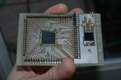
Christmas Eve afternoon was spent making the breakout board shown in the photo, and I had enough time before Christmas dinner to check that the board at least programmed correctly (which it did), so I don't think I screwed anything up too badly :-) This is the chip I intend to use as the CPLD on the ethernet board. It has more pins than I actually need, but the next size down is the (more expensive!) PLCC, and then to the 44 pin packages which don't have enough pins.
Apart from pin headers/SIL strips, everything is surface mount, using the passives I intend to use for the final board. The 3.3v power circuit (using a 3.3v low dropout regulator, no heatsink required since the current draw won't be that high) is also the one I intend to use on the final board. Decoupling capacitors are all 0603 sized which is as small as easily hand solderable. I want to get the passives down as small as possible so they don't get in the way too much when routing traces; 1206 is just a bit too big (and gave me a real headache when laying out the W5100 breakout board).
I probably won't get much more done on the project over the next week or two (too many Christmas/New Year type events going on) but hopefully by the end of the month I'll have the W5100, CPLD and memory all working on breadboard and will have sent the first packet.
Winston 10:28, 25 December 2007 (UTC)
Welcome to the wiki
In order to make it easy to document ongoing hardware projects for the Sinclair Spectrum, I've put this wiki into service. At the moment, it can only be edited by me... but in future, I hope there will be others interested in collaborating on the projects here, and MediaWiki makes it easy for others to edit, too.
Onto the most recent news. I've just received my order from Farnell for most of the parts needed to make the prototype ethernet boards. I intend to make a small number (about 8 or so) to allow me to develop ways to economically build boards (economic not just in money, but in time). Experience of hand-making a couple of diagnostics boards showed that this was a non-starter (it took FAR too long - a couple of hours per board at least to assemble!) so this time around, I've decided to use surface mount parts, and build my own reflow system (with a hotplate or a toaster oven - nothing expensive) to try and make the boards reasonably quick to assemble. I also intend to make a handful of prototypes, so I can get a few out to some Spectrum enthusiasts who want to be on the bleeding edge (!) and shake out any bugs.
But in this consignment, I have:
- 10 Xilinx XC9572 CPLDs, in 100 pin TQFP packages. 3.3 volt types (which have 5v tolerant I/O)
- 10 Am29F010 90ns 128kbyte flash memories. This is to hold the ROM code, and a set of applications to go with the board. These are in TSSOP packages.
- 10 IDT71024 128kbyte static memories. Extra workspace for networked applications. These are in SOJ (small outline, J-lead) packages.
- 3.3v linear regulator - to power the W5100 and the XC9572.
- Various surface mount passives (lots of capacitors, a few resistors, a few inductors).
- A couple of tools to make it a bit easier to do surface mount stuff (tweezers, nothing fancy)
- On back-order - 10 Tyco Mag45 RJ-45 sockets with integrated magnetics.
I already have plenty of some of the other parts - lots of 25MHz crystals, enough P and N channel discrete MOSFETs (for the ROMCS hold circuit), indicator LEDs etc.
I still need to get some card edge connectors, LaesQ suggested a suitable supplier (where he gets the connectors for the DivIDE).
The current plan of attack is to make a breakout board for one of the XC9572s, including a 3.3v regulation circuit, and breadboard a test circuit which will include a (DIP packaged) Am29F010, as well as a 1mbit static RAM, and the W5100 breakout board I built earlier. This will enable me to test that the Spectrum's bus doesn't get loaded too heavily (I've already noted that the W5100 puts some loading on the bus from earlier tests), and that the current draw isn't too high; the W5100 can use up to 180mA with the PHY at full power. Once any hardware issues are sorted out, then design the schematics/PCB for the first version of the board... then have PCB Train make 10 of them.
Winston 22:51, 21 December 2007 (UTC)
