Memory
Overview
The Sinclair Spectrum unfortunately doesn't have a formal sideways memory scheme. Instead, we just have the ability to page in external memory into the lower 16K of the Z80's address space, then manage this ourselves. Memory management is carried out by the CPLD, which looks after which pages are mapped where, and when to page in our memory map into the lower 16K address space.
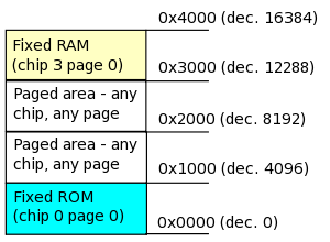
The Spectranet memory is arranged in 4K pages, with up to 4 chips (chips 0 to 3), each chip a maximum of 1Mbyte in size (the actual hardware uses a 128K flash ROM, a 128K static RAM and the W5100's 32K). The flash ROM is chip 0, the W5100 is chip 1, chip 2 is unused at present and chip 3 is the static RAM. Two pages are permanently mapped into the lowest 4K (flash ROM) and highest 4K (static RAM). This is to guarantee to software that certain memory will always be in the same place; page 0 of flash is used to contain initialization routines, the socket library and interrupt handlers. Page 0 of the static RAM is to hold general purpose workspace, system variables, and the jump table.
The middle 8K of this area is the paged area. Any page of any chip can be paged into page area A (0x1000 to 0x1FFF) or page area B (0x2000 to 0x2FFF).
Selecting pages for the paged area
Three registers are provided for selecting pages - page register A, which contains the page for 0x1000 to 0x1FFF, and page register B for 0x2000 to 0x2FFF. The third register is the chip select register. Bits 0 and 1 select the chip in page area A, and bits 2 and 3 select the chip for page area B.
The following I/O ports are used:
- Port 0xE9 - Memory page for area A (8 bits)
- Port 0xEB - Memory page for area B (8 bits)
- Port 0xED - Chip select for both areas (4 bits)
The complete 8 bits of the port address is decoded, so only OUT instructions to these specific ports will work (unlike older peripherals, which tend to only decode at most 3 bits of a port address). The paging registers are write-only; the currently selected page should be stored in the system variables area.
A code example to select page 3 of the static RAM into page area A:
LD A, (SYS_CHIPSELECT)   ; get the currently selected chips
OR 3                     ; set lower 2 bits
OUT (0xED), A            ; set chip select register
LD (SYS_CHIPSELECT), A   ; store new value of chip select register
LD A, 3                  ; page 3
OUT (0xE9), A            ; set page register for area A
LD (SYS_PAGEAREA_A), A   ; save register value in RAM
TODO: A routine will be provided to allow for "longcalls" (page in a specific page, and call it, and restore on return).
