Current events
Mulling over the PCB layout
This evening, I decided to have a look at component placement, and see if I want to do is actually possible. My target is for a PCB no larger than 100mm by 60mm. For a board that sticks out of the back of the Spectrum (rather than going underneath, a la Interface 1), there are size constraints. The right hand side of the PCB can't overhang the edge connector by much or you'll never get the 9v power plug in. On the left, you can't go too far or you get in the way of the MIC/EAR plugs on the 48k, or in the way of the RGB cable on the 128k toast rack. I don't own an Amstrad Spectrum so I don't yet know of any additional size constraints it'll bring. As for the depth of the board, 6cm is about the most without causing mechanical problems if stuff is connected to the edge connector.
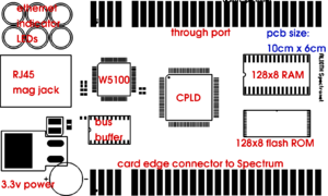
This means the board will be extremely dense. To get an idea, look at the mock up on the right. It doesn't look too bad till you view it actual size.
This is going to be a challenging PCB to lay out, it'll probably be several days work to do it. It must be at least 4 layer; the board would be twice the size to do it with two, and the through port would have to be much more complex (that makes it expensive). Around the W5100 things get hairy: traces for the through port must avoid the 25MHz crystal (not shown, but it'll be above the W5100), and also the analogue supply for the W5100...which sits right between the 4 left most edge connector pads. On the flip side, 4 layers is a huge luxury (I'm used to doing everything with two) as well as targeting a manufactured board rather than a home made board. A manufactured board means I can use far smaller vias, and I can put them underneath surface mount chips. Having a 4 layer board also means that I will have a proper ground plane for a change, which will make the W5100 perform much better (it's sort of marginal on my 2 layer home made breakout board). Even with the proper ground plane and better decoupling that I can do with a factory made PCB, I'm still going to keep the 74HCT245 buffer on the W5100's data bus - it would be a false economy to delete it. Horowitz and Hill in their book, The Art of Electronics always admonish their students to design for the worst case.
Hardware finalization and core library testing
Hardware
The last few days have been adding the bits to the CPLD that are shown in the schematic, but not actually added to the hardware I have on my work table. In particular, I've added the global execution trap enable input. The point of this is to allow for the assembly of new boards using a Spectrum as the flash programmer. When building a board, the first thing that has to be done is to configure the blank CPLD. The flash, being surface mount, can't be programmed until it's soldered onto the board, so immediately after the CPLD is configured, you've got no ROM. What would happen on power up is that the Spectrum would immediately crash - the RESET condition would be trapped, but the entirety of the flash ROM would be nothing but RST 0x38 instructions. So there needs to be some way of disabling the execution trap - the simple way is to have a jumper that allows you to disable the trapper (but leave all other functions enabled). Then the ROM image can be flashed, perhaps loaded from tape, but in my case, I'll put it on an IDE device connected to a DivIDE on the through port.
I've made some other changes, such as changing the HOLD ROMCS pin to an open drain output. This means only one P-channel MOSFET is required to do the 3.3v to 5v level shift to hold ROMCS high when the ROM is paged in (rather than the previous scheme that used two transistors). As well as slightly reducing the component cost, it opens up more space for trace routing on the board.
Partial port decoding is teh suck. Unfortunately, Sinclair did it a lot, and it got me in trouble when I connected the 128k toast rack Spectrum to the prototype. The ports I'm using, if the upper half of the address bus wasn't set just right conflicted with the 128k memory paging, causing an instant crash. This could be fixed in software (by using OUT (c), r, and setting B to 0x80). But the trouble is, it's very very hard not to conflict with some piece of hardware due to the number of devices that only check one or two bits out of the 16 available.
I also found out that the Plus D was using a lot of ports, some directly conflicting with mine, too. I would like this board to work with the Plus D (I'd really like to have it work with the DivIDE, DivIDE+, Plus D, ZX Interface 1, and the 128k +3's disc drive). To do this it's looking increasingly like I won't be able to have my I/O ports in the lower 8 bits; I'll probably have to use ports 0xF0FF, 0xF1FF, 0xF2FF and 0xF3FF for the 4 I/O ports I need. Since I'm already going to have to do LD BC, port/OUT (c), r anyway, even if using the lower address bus, the slightly unconventional port usage won't really hurt.
I've also been pricing up PCBs. In quantities of 50, the price for a 4 layer board vs. a 2 layer board is really not much more (once you add the through port - a 4 layer board with a simple edge connector on the back, vs a much larger 2 layer board with a riser for the through port like the DivIDE+ - a 4 layer PCB is less expensive), so I'm pretty convinced a 4 layer PCB is the way to go. It'll allow for a decent ground plane even ignoring the extra routing options the extra two layers will allow. I need to mock up some designs in PCB to see how it will all fit together, probably some time next month. If Rich Mellor can sell 100 DivIDE+ systems, I don't think I'm taking a huge financial risk if I order up boards 50 at a time from PCB Train.
Software
I've been debugging the code I wrote on the plane to Houston. What I did is made a simple test program, that assembles all the W5100 routines into RAM, and tests them in RAM. Then I just load this program into RAM using the *F command I added to the experiment ROM (which I currently have loaded). It's very handy - I can just sit at my Linux workstation, add some test code, assemble, type *F on the Spectrum and use the 'ethup' utility to send the program over the ethernet cable to the Spectrum. Run the tests, then reset the Spectrum for the next test. It makes it very fast to try out the code on the real hardware, since the test program loads instantly over ethernet.
The code mostly worked, but there were a few bugs that needed to be fixed, most of them pretty simple and caused by omissions, rather than discovering something really broken about the design.
The library test routines so far can be viewed in WebSVN here [1]. So far, this tests some of the core routines - opening and closing sockets, receiving and sending data over a TCP socket.
I want to get the basic TCP and UDP code tested before I get the prototype PCBs made, to ensure there are no bad showstoppers with the current breadboard prototype, so that's why I've got some focus on the software before the first PCBs have been made.
Winston 21:33, 24 February 2008 (UTC)
A solidification of the plans
While I've been away, I've not quite completely left things alone.
For example, I had quite a bit of time in planes and stuck in airport terminals. My 12in. Apple PowerBook is not only small - fitting neatly into a pocket of my backpack (I've never seen the need for a laptop bag, they scream 'Steal Me!') - but also runs gschem just fine.
So I passed the time on the plane from Houston to Salt Lake City and back making symbols for the memory and the W5100, and also experimenting with transforming a schematic into a netlist and PCB layout with my own symbols. Then, I made the CPLD symbol, and on the plane from Houston to Gatwick, started on the schematic proper. I nearly missed the plane from Gatwick back to the Isle of Man, I got so engrossed.
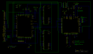
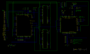
If you go to the image on the right, make sure you download it and zoom in fully, it's about 3000x2000 pixels or so - with so many pins on the chips the schematic gets a bit large. On this schematic, I'm explicitly showing power pins (often, people omit them from schematics). There are no less than 3 voltages used - 5v, 3.3v and 1.8v, as well as analogue 3.3v and analogue 1.8v - no less than 5 power nets. Also, there's a bit more than the usual decoupling used, so I want to show this explicitly. (I'll modify gschem's 74245 symbol to include power). It's a work in progress and not yet complete; in particular, I've not yet decided the pin assignments for the CPLD, nor the precise details of the reset circuit, and I need to finalise the ROMCS circuit (and have it compatible with the Spectrum +3). The through port is not shown on the schematic (and I don't intend to show it, except for indicating where A15OUT should connect).
Once the final prototyping is complete, and I've tested the basic socket library (to shake out any hardware problems I've not yet discovered), the next step will be the PCB. I intend to make 10 prototypes, using PCB Train as a board maker (the same board maker used for Papaya Labs DivIDE). My plan for the PCB is to make it pretty small - around 10cm by 5cm - if I can keep it short, then the through port can be just on the back of the PCB. This may require a 4 layer board.
While in Houston, I visited EPO - it's a handy component shop with all sorts of interesting stuff. I picked up a few 74HCT245 ICs while I was there - if you read down to some older entries here, you'll see the problems encountered with when 0xFF is read from the W5100 - which doesn't have the oompf to drive the Spectrum's long bus (with all the parasitic capacitance that implies). The '245 allows me to separate the Spectrum's bus from the W5100's data I/O pins, so the W5100 is only driving the lines to that one chip, with nice high impedance FET inputs. Putting the '245 on the breadboard completely solved the problem, even after removing all the 4.7k pull up resistors. I've decided I'll use the '245 rather than putting a bidirectional buffer into the CPLD, since the bidirectional buffer uses a heap of macrocells (about 25!) I could use for something that would take several chips to implement.
Winston 21:55, 19 February 2008 (UTC)


